
Anatomy of a Coiled Cord
A Koiled Kord™ (Coiled Cord, Retractile Cord) is composed of cordage specifically designed to be formed and cured into a helical shape in such a manner that it tends naturally and repeatedly to return to its original shape/with each adjacent individual coil touching the next in close proximity after having been stretched or extended to its designed operational length one or more times. The combination of the individual conductors, insulation, shields, fillers, strength members, and jacket, varies according to the individual application, but in all cases, the construction is designed to account for the mechanical stresses applied during the extension/retraction cycle expected for the cord, as well as the electrical and environmental performance required.
In order to specify a Koiled Kord™, it is first necessary to understand the various nomenclature associated with one. It is also necessary to understand your application and the mechanical and electrical performance you wish to achieve, as well as the environmental conditions under which you wish the Koiled Kord™ to perform.
A Koiled Kord™ has three basic physical components. There are two individual straight ends; End 1 and End 2, and the helical coil (Please see Figure 1). Figure 1A depicts a Koiled Kord™ with Tangent ends, and Figure 1B depicts a coiled cord with Axial ends. A Koiled Kord™ could have two Tangent ends, two axial ends, or one of each. Tangent ends are by far the most common. Axial ends are slightly more di cult to manufacture, and are thus slightly more expensive. Koiled Kords™ with one of each type of end are uncommon, but it is possible that certain mounting constraints may at times dictate such an arrangement.
There are several Physical Dimensions associated with a Koiled Kord™, which may be necessary to specify. When specifying these dimensions, it is important to specify only those dimensions that are critical to your design. Allow all other dimensions to be determined by Whitney Blake’s experienced Design Engineers.
The Outside Diameter (OD) of the cordage itself may be critical to your design for any number of reasons. Perhaps it must be compatible with a certain connector or an access through-hole. Perhaps your marketing team has determined a specific diameter that will be well accepted by prospective customers. Whatever the reason, if you have reason to specify the Cordage OD, be sure to do so. If not, leave it up to Whitney Blake, because there are many other variables which aff ect the final cordage OD, or which are aff ected by it.
The Inside Diameter (ID) of the coil may be critical to your design, as may be the Outside Diameter of the coil. In some cases, both may be critical. The Coil ID is measured across the inside edges of the coils. The Coil OD is measured across the outside edges of the coils. In the design and manufacture of a quality Koiled Kord™, there are certain relationships between the Cordage OD and the Coil OD/ID within which we must remain. It is not possible to coil a large cordage OD into a small coil OD, for instance, because the cordage cannot be bent over a small radius. By the same token, it is not advisable to coil a small cordage OD into a large coil OD, because the finished product will not hold its coiled shape well, and it will exhibit poor retraction performance.
The Retracted Length, and the related Extended Length of the coiled section of the Koiled Kord™ will certainly be critical to your design, and should always be specified.. These two are closely related. Our rule of thumb for the ratio of Extended Length to Retracted Length is 5:1, but it varies in practice to less than 4:1 and greater than 6:1. Please note that it is inadvisable to fully extend any Koiled Kord™ to the point that it completely, or even nearly straightens the cordage out. This could damage the cord to the point that it will no longer retract satisfactorily. For design purposes, specify the retracted length.
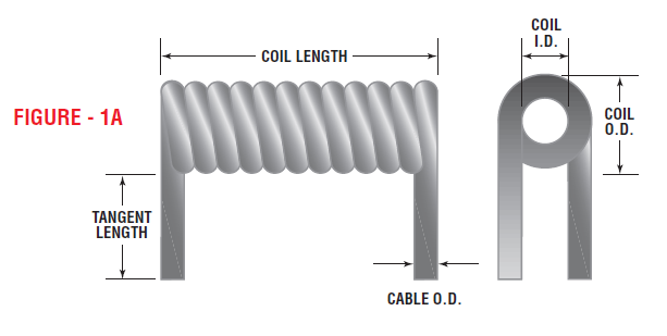
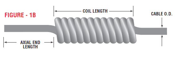
The End Lengths will also certainly be critical specification parameters. End Lengths are measured di erently for tangent and axial ends. Tangent end lengths are measured from the outside edge of the Koiled Kord™ nearest the end of the tangent (Please see Figure 1A). Axial ends are measured from the end of the Koiled Kord™ with the radius of the axial bend laying flat on a surface, such as a table, and the end of the Koiled Kord™ abutting the edge of the surface (Please see Figure 1B). End Lengths may be specified as minimums, or they may be given a tolerance.
Additional dimensions may necessarily be specified, depending on the extent of end work to be completed on any Koiled Kord™. These dimensions may be referenced to the end of the cable, to the end of the coiled section, or to other existing features, such as a molded strain relief, or an applied watertight fitting. These additional dimensions include, but are not limited to, ROJ (Removal of Jacket), Cutback of individual conductors or other cordage components, Strip Length (the length of insulation removed from individual conductors for tinning or application of contacts).
ROJ may be specified to remove a certain length of jacket material from the end of the cable, or leave a certain length of jacket beyond the end of the coiled section some other feature. The ROJ will be performed in such a manner as to remove the jacket only, and in some cases a paper separator or shield, but to leave the remaining cable core undamaged for further operations by Whitney Blake, or by the customer at its own facility.
Cutback may specify to cut fillers, stay cords, or other components back to the jacket edge, or may specify a distance from the jacket edge. In some cases, individual conductors, or other components may be specified with diff erent cutback lengths to accommodate a specific application.
Strip Length defines the length the insulation, or in some cases the shield and insulator for coaxial conductors, must be removed, hi some cases, this is the last operation required by the customer, but frequently, this is in preparation for some additional step such as twisting and tinning the strands of the conductor or applying a contact by some method such as crimping or soldering.